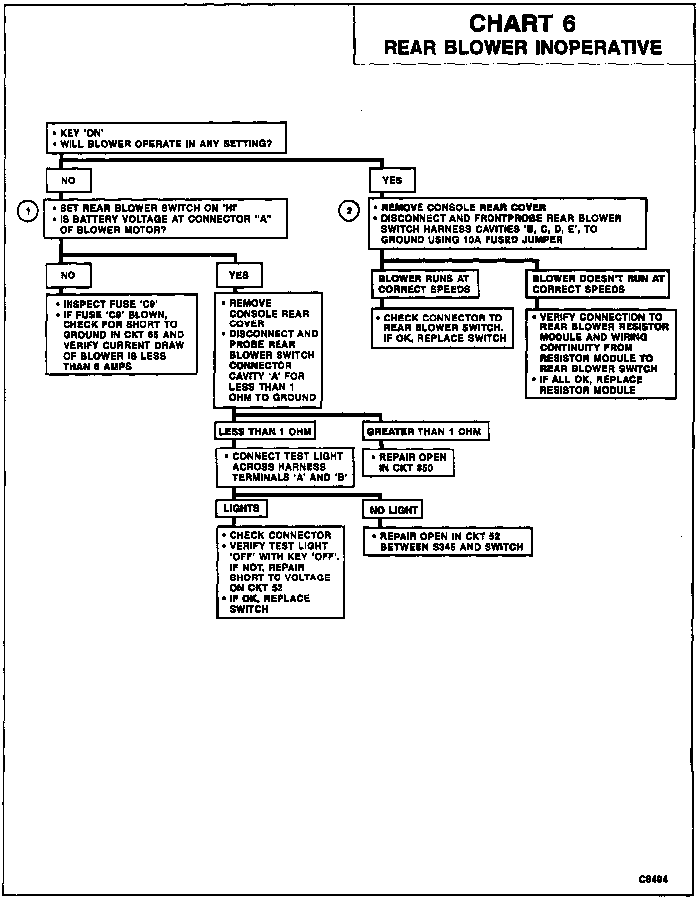
Chart 6 Rear Blower Inoperative
CIRCUIT DESCRIPTION
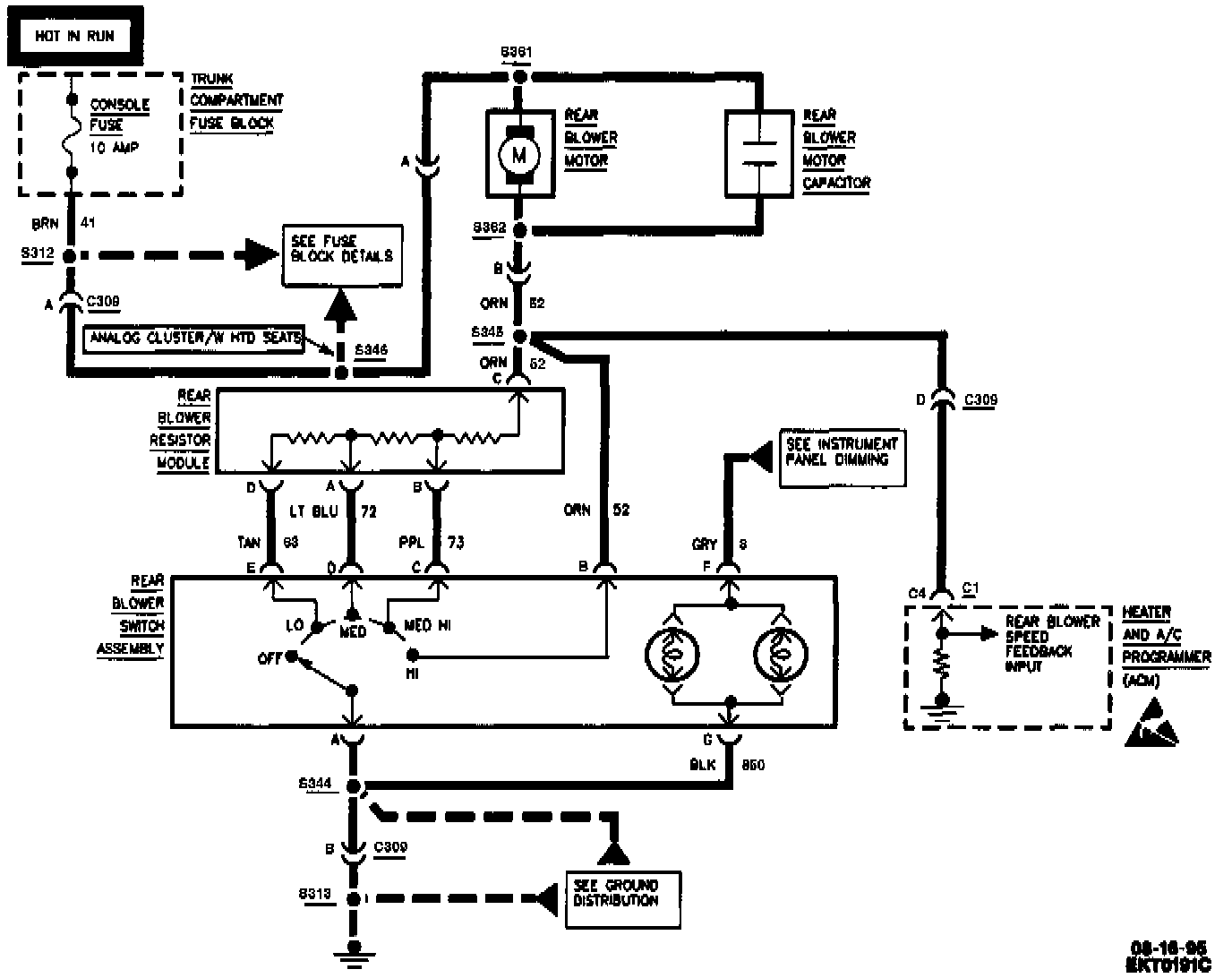
Power from fuse CONSOLE FUSE is applied to the blower motor and ground is supplied through the switch. The blower speed is controlled by varying the circuit amperage using a series of three resistors contained in a module. The Air Conditioning Programmer (ACM) receives a feedback voltage signal, but this has no effect on rear blower operation.
TEST DESCRIPTION
Numbers below refer to circled numbers on the diagnostic chart.
1. If CKTs 52, 850 and the "Hi" position of the switch have continuity then the reading will be nearly zero. As slower speeds are selected, the blower motor ground path passes through more series resistors in the module and results in increasing voltages at S345. Battery voltage should be read in "OFF."
2. If a resistor in the module is open, all cavities beyond that point will also be open. If cavity "E" operates blower, then fault is in the switch or wiring to the switch.