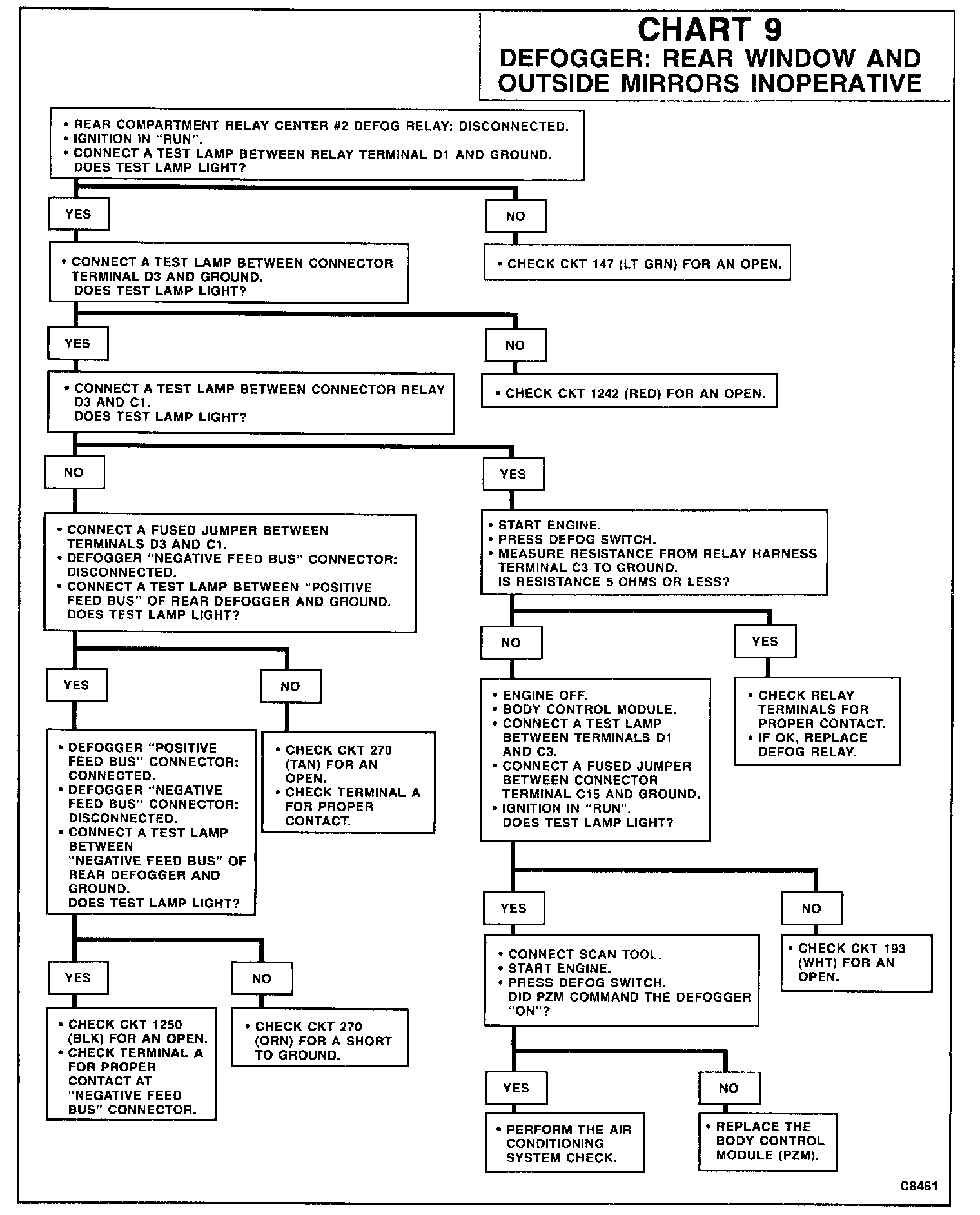
Chart 9 Defogger: Rear Window & Outside Mirrors Inoperative
CIRCUIT OPERATION
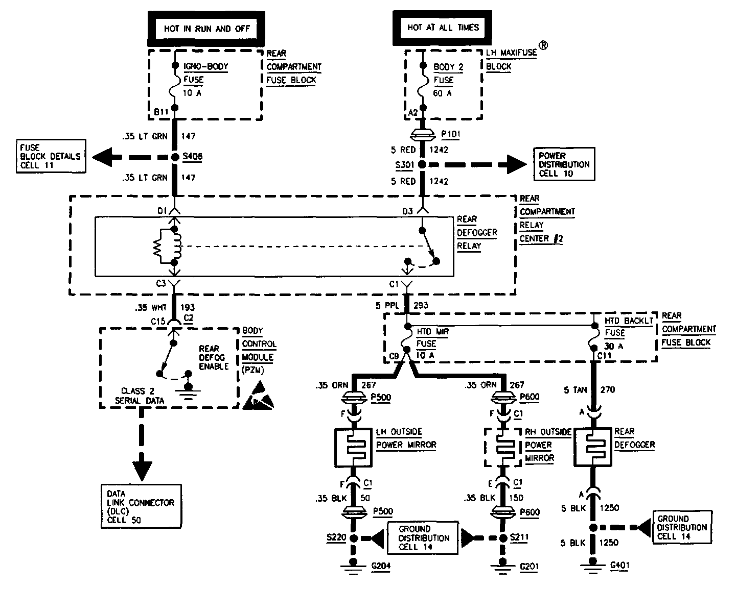
The rear defogger system consists of defogger relay, rear defogger grid, body control module, outside mirror defoggers, instrument panel cluster and related fuses and wiring.
When the rear defogger is turned ON, the IPC confirms that the engine is running. The IPC receives engine status from PCM via the class 2 data line. When engine status has been confirmed, the IPC turns ON the defogger-ON LED and commands the Body Control Module (PZM) to turn ON the defoggers via the class 2 data line. When the PZM receives the command, the defogger relay coil is ground through the PZM terminal C2.
IPC also controls the timing cycle function. When the 5 or 10 minute cycle has elapsed, the IPC switches OFF the defogger-ON LED and commands the PZM to turn OFF defoggers via the data line. When the PZM receives the command, ground is removed through PZM terminal C2.
When the PZM grounds the defogger relay coil, the relay energizes causing the relay contacts to close. Battery voltage from the BODY 2 Fuse is applied to the HTD MIR and RR DEFOG Fuses. The HTD MIR Fuse provides battery voltage for the outside mirror defoggers. The RR DEFOG Fuse provides battery voltage for the rear window defogger grid.