Front Suspension
^ Tools Required:
- J 35315 Ball Stud Separator
- J 35551 Ball Joint Nut Wrench
- Or Equivalents
REMOVE OR DISCONNECT
1. Raise vehicle and support frame with jackstands.
2. Tire and wheel assembly.
3. Road sensing suspension position sensor from lower control arm.
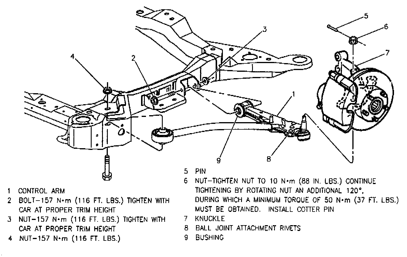
4. Ball joint from knuckle.
5. Drill out three rivets retaining ball joint starting with 1/4-inch drill bit and finishing with 1/2-inch drill bit.
6. Remove joint.
INSTALL OR CONNECT
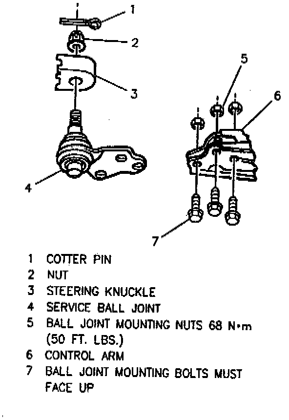
1. New ball joint into control arm.
2. Ball joint-to-control arm bolts.
^ Tighten:
- Ball joint-to-control arm nuts to 68 Nm (50 ft. lbs.).
- Ball joint nut to 10 Nm (84 inch lbs.) using J 35551 90° to torque wrench. Tighten nut an additional 120°. When tightening nut a minimum torque of 50 Nm (37 ft. lbs.) must be obtained. If 50 Nm (37 ft. lbs.) is not obtained, inspect for stripped threads. If threads are satisfactory, replace ball joint and knuckle. If required, turn the nut up to an additional 60° to allow for installation of the cotter pin.
3. Road sensing suspension position sensor to lower control arm.
4. Tire and wheel assembly.
^ Tighten wheel nuts to 140 Nm (100 ft. lbs.).
5. Lower vehicle.