Without Commercial Chassis
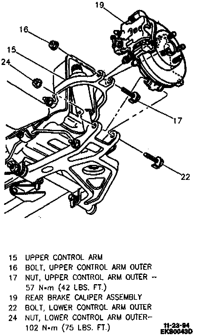
REMOVE OR DISCONNECT
1. Raise vehicle.
2. Wheel and tire.
3. Caliper and suspend. Refer to Brakes.
4. Rotor.
5. Hub and bearing assembly.
6. Support outboard end of lower control arm with screw jack to relieve spring load.
CAUTION: Jackstand must be of adequate strength to support vehicle weight. Jackstand must be securely positioned or personal injury may result. Place Jackstand under front of vehicle to prevent vehicle from falling from hoist.
7. Lower shock absorber bolt.
8. Stabilizer link from control arm.
9. Rear toe link outer bolt and discard. Bolt is not reusable.
10. Lower control arm outer nut and bolt.
11. Upper control arm outer nut and bolt.
12. Wheel speed sensor cable bracket from knuckle.
INSTALL OR CONNECT
1. Wheel speed sensor cable bracket to knuckle.
2. Position knuckle in upper control arm and install bolt and nut.
3. Position knuckle in lower control arm and install bolt and nut.
4. New rear toe link outer bolt. Do not tighten at this time. Toe link must be tightened in designed position to reduce wind up in bushings.
5. Stabilizer link to control arm.
6. Lower shock absorber bolt.
7. Hub and bearing.
^ Tighten:
- Upper control arm outer nut to 57 Nm (42 lb ft).
- Lower control arm outer nut to 102 Nm (75 lb ft).
- Toe link outer bolt to 75 Nm (55 lb ft).
- Lower shock nut to 102 Nm (75 lb ft).
- Lower stabilizer link bolt to 60 Nm (44 lb ft).
- Hub mounting bolts to 70 Nm (52 lb ft).
8. Rotor.
9. Caliper and new caliper bracket mounting bolts. Refer to BRAKES.
^ Tighten:
- Caliper mounting bracket bolts to 113 Nm (83 lb ft).
- Parking brake cable bracket bolt to 43 Nm (32 lb ft).
10. Wheel and tire.
^ Tighten wheel nuts to 140 Nm (100 lb ft).
11. Lower vehicle.